The Coefficients of Steel and Concrete

In our previous articles, we discussed the mineral components of steel and concrete. In this article, we will dwell further into the element’s composition and how they are affected when there are changes in temperature.
All elements on our planet change in size when the temperature increases or decreases; although very minimally, but when dealing with the engineering of buildings and bridges, this change, however slight, could become catastrophic if not properly addressed and compensated for.
Such is the case for iron, steel, and concrete. They expand and compress as the temperatures increase and decrease, respectively. A good way to remember which direction they are moving is: increase = expansion and decrease = compression.
Each element has a specific temperature coefficient. Even if it is just a tiny amount, if there is not enough room for the material to ‘stretch’ (expand) or decrease (compress), it will show signs of wear, and after a time, it could break and everything above it will collapse. In this table, we can see how much materials expand or contract per degree.
For the mathematically inclined:
If 1 mile = 5280 feet, then 1 mile equates to (12 5280’) = 63360”.
1 inch of steel expands 0.00000645” for every 1 degree Fahrenheit increase in temperature; therefore, 63360” 0.00000645” = 0.408672 inches per degree.
Thus, as the weather gets warmer, steel will expand 0.408672 inches for every one degree in temperature.
Material Expansion and Compression MUST be Compensated for in Construction!
In this Pipes and Tubes Temperature Expansion table, you can see the minimal effect of stresses that are placed on certain metals; however, if not compensated for, the integrity of the elements will be compromised.
The question then is, what happens to bridges that have steel columns? If they expand and compress without freedom of movement from temperature differentials, the steel will eventually crack and can lead to a defective bridge.
Enter Bridge Bearings
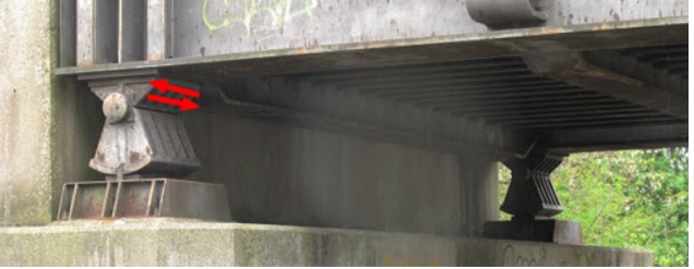
The answer is bridge bearings (previously called rollers) that allow for the stresses of the steel to move in either direction.
In the photo below, a cylindrical bearing is placed between the vertical supports, called piers, that would otherwise be permanently fastened to each other. The bearings in between them allows for the bridge to expand and compress freely.

In summary, the function of a bridge bearing is to transmit and distribute superstructure loads to the substructure (bridge) and permit the superstructure to undergo the necessary movements of stress, which can consist of compression, shear, and rotation, consequently preventing overstress, which would otherwise compromise the structural integrity of the bridge.
Bridge Bearing Types
There are several types of bridge bearings utilized and are dependent upon a number of different factors, including the length of the bridge span. The oldest bridge bearing involves just two plates resting on top of each other.
Here is a good illustration of bridge-bearing plates. It depicts quite well how the plates are stacked on top of each other, as well as the limitations placed on it, such as the guide block, which prevents the plates from sliding off. This plate scheme can be seen on many bridges, especially those that span highways and parkways.
A common form of a modern bridge bearing is the elastomeric bridge bearing, which is more common today. Besides freedom of material stress, they also extend the life of the bridges by reducing continuous wear and tear on the bridge materials.
The Bay Bridge collapse after the 1989 7.1 magnitude Loma Prieta earthquake is a perfect example when using inadequate bearings for a structure, especially within an earthquake zone. The use of elastomeric bridge bearing should help to alleviate the engineering errors that caused this part of the road to collapse.
As you travel, you might want to locate the bearings on the bridges you drive on, and now, have a better idea of what those things are that are attached to your bridge.

 If you’re looking for a gemstone that truly showcases the uniqueness of nature, an amber gem is a perfect choice for you. With a history of tens of thousands of years, amber is one of the oldest minerals that have been used for jewelry. Popular for its golden hues and simplicity, this gemstone is a must-have for collectors.